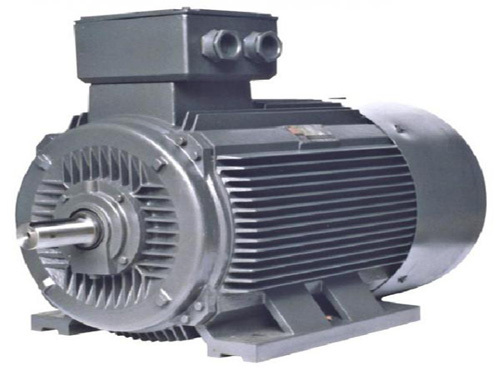
Three-phase asynchronous motor belongs to the motor transmission product type, because the rotating magnetic field of the rotor and stator of the three-phase asynchronous motor is in the same direction and different rotating speeds as optional equipment, there is a slip rate so it is called a three-phase asynchronous motor. Today Xiao Bian came to introduce the working principle of the three-phase asynchronous motor of the motor drive in detail, hoping to help the user to better use the three-phase asynchronous motor.
When the three-phase stator windings of the motor (each with a 120-degree electrical phase difference), after the three-phase symmetrical alternating current is passed, a rotating magnetic field is generated. The rotating magnetic field cuts the rotor windings and thus induces a current in the rotor windings (the rotor windings are closed. Pathway), the current-carrying rotor conductor will generate electromagnetic force under the action of the rotating magnetic field of the stator, thus forming electromagnetic torque on the rotating shaft of the motor, driving the motor to rotate, and the direction of rotation of the motor and the direction of the rotating magnetic field.
When a conductor cuts a magnetic field in a magnetic field, an induced current is generated in the conductor, and the name of the "induction motor" comes from this. The combined action of induced currents and magnetic fields applies drive to the rotor of the motor.
We let the closing coil ABCD rotate in the magnetic field B around the axis xy. If the magnetic field is rotated in the clockwise direction, the closing coil undergoes a variable magnetic flux, generating an induced electromotive force, which generates an induced current (Faraday's law). According to Lenz's law, the direction of the current is: The effect of the induced current always hinders the cause of the induced current. Therefore, each conductor receives a Lorentz force F that is opposite to the direction of motion of the induced magnetic field.
A simple way to determine the direction of each conductor's force F is to use a right-handed three-handed designation (the magnetic field acts on the current and places the thumb in the direction of the induced magnetic field, with the index finger as the direction of force. Place the middle finger in the direction of the induced current. The closed coil is subjected to a certain amount of torque so as to rotate in the same direction as the induction sub-field, which is called a rotating magnetic field, and the electric torque generated by the closing coil rotation balances the load torque.
Rotating magnetic field production
The three sets of windings are 120 degrees out of phase with each other and each set of windings is powered by one of the three phase AC power supplies.
The windings and the alternating current with the same electrical phase shift cross each other, each group produces an alternating sine wave magnetic field. The magnetic field is always along the same axis. When the winding current is at the peak, the magnetic field is also at the peak. The magnetic field produced by each set of windings is the result of two magnetic fields rotating in opposite directions. Both magnetic fields are constant and equal to half of the peak magnetic field. This magnetic field. Rotate during the power supply period. Its speed depends on the power frequency (f) and the number of pole pairs (P). This is called "synchronous speed"
Slip rate
The drive torque is only present when the closed coil has induced current. The torque is determined by the current of the closing coil and only exists when the magnetic flux in the ring changes. Therefore, there must be a speed difference between the closing coil and the rotating magnetic field. Therefore, a motor that operates in accordance with the above principle is called an "asynchronous motor." The difference between the synchronous speed (ns) and the closing speed (n) is called the "slip" and is expressed as a percentage of the synchronous speed. s = [(ns - n) / ns] x 100% (s is a subscript) During operation, the rotor current frequency is the power supply frequency multiplied by the slip rate. When the motor is started, the rotor current frequency is at a maximum, equal to the stator current frequency.
The rotor current frequency gradually decreases as the motor speed increases. The slip in a steady state is related to the motor load. It is affected by the supply voltage. If the load is low, the slip rate is small. If the motor supply voltage is lower than the rated value, the slip rate increases.
The synchronous speed of the synchronous three-phase asynchronous motor is proportional to the power frequency and inversely proportional to the logarithm of the stator.
For example: ns=60 f/p type ns-synchronous rotation speed, unit is r/lmin f-frequency, unit is Hz, P pole pair number is given at 50Hz, 60Hz and 100Hz industrial frequency, corresponding to different number of magnetic poles Rotating magnetic field speed or synchronous speed.
In fact, even voltage. Correct, if the power supply frequency is higher than the rated frequency of the asynchronous motor, it may not be able to increase the motor speed. It must first determine its mechanical and electrical capacity. Due to the slip, the speed of the asynchronous motor with load is slightly lower than the synchronous speed given in the table. Changing the rotation direction of the motor and changing the phase sequence of the power supply can be realized, that is, switching the three-phase voltage passed to the motor to any two phases in the motor terminal.
Because the induced current in the rotor coil of the motor-driven three-phase asynchronous motor is generated due to the relative motion of the rotor conductor and the magnetic field. The rotational speed of the three-phase asynchronous motor will not be synchronized with the rotating magnetic field, nor will it exceed the speed of the rotating magnetic field. If the rotating speed of the three-phase asynchronous motor rotor is equal to the rotating magnetic field rotation speed, then there will be no relative movement between the magnetic field and the rotor, and the conductor cannot cut the magnetic force line, so no induced potential and current will be generated in the rotor coil. In a magnetic field, the asynchronous motor rotor conductor will not be subjected to the electromagnetic force to rotate the rotor. Therefore, the rotation speed of the three-phase asynchronous motor cannot be the same as the rotating magnetic field, and it is always smaller than the synchronous rotation speed of the rotating magnetic field. However, in special operating modes (such as generator braking), the rotor speed of the three-phase asynchronous motor may be greater than the synchronous speed.
Start and run
(1) When a three-phase asynchronous motor is connected to a three-phase AC power supply (with a phase difference of 120 degrees), the three-phase stator windings flow through the three-phase magnetomotive force (stator rotation magnetomotive force) generated by three-phase symmetrical currents and generate The magnetic field is rotated, and the magnetic field rotates in the clockwise direction along the inner space of the stator and the rotor at the synchronous rotational speed n0.
(2) The rotating magnetic field and the rotor conductor have a relative cutting motion. According to the electromagnetic induction principle, the rotor conductor (the rotor winding is a closed path) generates an induced electromotive force and generates an induced current (the direction of the induced electromotive force is judged by the right-hand rule).
(3) According to the law of electromagnetic force, under the action of induced electromotive force, induced current in the rotor conductor will be generated in the direction of the induced electromotive force. The current-carrying rotor conductor is subjected to an electromagnetic force in the magnetic field generated by the stator (the direction of the force is determined by the left-hand rule). The electromagnetic force forms an electromagnetic torque on the motor rotor shaft and drives the motor rotor to rotate in the direction of the rotating magnetic field when the motor With mechanical loads on the shaft, mechanical energy is output outward. Since there is no magnetic flux in the short-circuit ring portion leading than the magnetic flux in the short-circuit ring portion, the direction of rotation of the motor is the same as that of the rotating magnetic field.
Aws E316-16 Welding Electrodes
Description:
E316-16 Welding Electrodes deposited metal is a stable austenite structure containing 18Cr-12Ni-2Mo. Due to the Mo element content in it, it shows excellent properties in resisting corrosion of acetic acid, sulphuric acid, phophate acid as well as salt, and has good high temperature crack-resistance.
Both AC and DC can be applied and it can be used for all position welding with excellent welding performances and good mechanical properties.
Applications:
AWS E316-16 Welding Electrodes is suitable for welding the parts of chemical industry and power engineering, such as A1S1 316 Steel, SUS 316 steel etc.
Attention:
1. Before welding, the welding electrodes should be baked at the temperature from 300 to 350 ℃ for one hour.
2. The stainless steel brush must be used to clean the weld seam, in order to avoid iron fillings penetrating there to affect its quality
AWS E316-16 Welding Electrodes
Aws E316-16 Welding Electrodes,316L-16 Welding Electrode,316L-16 Welding Rod,E316-16 Welding Electrodes
Dingzhou Jinlong Metal Production Co., Ltd. , http://www.weldingelectrodefactory.com