Vacuum HIRFL-CSR Ultra-high Vacuum System Yang Xiaotian, Zhang Junhui, Meng Jun, Zhang Xinjun, Zhang Xiping, Hou Shengjun, Hu Zhenjun, Niu Zhiwei, Hao Yanqian, Wu Huimin (Modern Institute of Physics, Chinese Academy of Sciences, Lanzhou, Gansu, China) The national "Ninth Five Year" major scientific project undertaken by the Institute is the Lanzhou Heavy Ionizer Cooling Storage Ring (HIRFL-SR) currently under construction. The device consists of four parts: two storage ring-primary rings (CSRm) and experiments. The ring (CSRe) and the main ring injection line and the secondary beam transmission line (RIBLL beam transmission line) connecting the main ring and the experimental ring are the layout diagrams of the vacuum system of the large-scale device. It is necessary to ensure that the overweight ion has a long storage life. The average vacuum degree of the two rings is required to reach 6 (10"Pa.) to achieve such a high degree of vacuum on large systems. This is the first time in large-scale installations in China. According to the technical design of the HIRFL-SR ultra-high vacuum system, we carry out The prototype development, and the establishment of ultra-high vacuum laboratory, configure the necessary large and medium-sized equipment for a variety of research and development, experimental work, in certain Under the premise of inspection, step by step, according to the scheduled plan, the entire system will be completed in 2004, a prototype developed CSRm bipolar iron vacuum chamber prototype 109Pa ultra-high vacuum experience, according to HIRFL-: SR ultra-high vacuum system technology design program, We first developed a CSRm bipolar iron vacuum chamber prototype, and obtained a vacuum of K 109Pa on this prototype, which has reached the desired target (The development process and results of this prototype have been introduced in other articles 1/16CSRm. Prototype cell block quadrupole iron (focusing lens) We take 1/16 of this as a second prototype. This prototype includes a diode vacuum chamber, a quadrupole iron vacuum chamber, and 2 pump chambers ) and 3 section bellows. The main vacuum exhaust system is composed of 2 plasma ion pump (ULVAC, 33L/s) and 4 titanium sublimation pumps (designed by ourselves, 2000L/s). Due to the need to withstand high temperature baking, 1 Complete oil-less turbomolecular pump (VARAN, 550L/s) roughing unit is separated from the main system by an all-metal sealed plug-in valve (VAT, CF-150) and is controlled by two IE514s. M52 vacuum gauge (ley-bold) with a separate installation 1 The quadrupole mass spectrometer (Pfeiffer Inc., qmg422) monitors the residual gas spectrum before and after baking. Table 1 Bake Displacement at Each Point of the Bicondium Iron Vacuum Chamber During the baking process, the degassing of the regulator and the mass spectrometer filaments is repeated several times. With 2>29 A current, the filaments of the titanium sublimation pump are degassed and circulated.At the middle of the baking, the sputter ion pump is started to close the all-metal sealing plug plate valve at the end of the insulation period, and the rough exhaust system is cut off. At ltPa, the current of the 4 Titanium sublimation pump filaments was adjusted to 48A, corresponding to a voltage of about 5V, and the filaments were sublimated for 1 5 min. The system vacuum was reduced due to the evaporation heat, but it quickly recovered. The baking knot was a prototype photograph, The lower right corner is the vacuum reading of the system for 1 month. 2 The establishment of the ultra-high vacuum laboratory and the experimental work The area of ​​the CSR ultra-high vacuum laboratory is about 500m2, of which the ultra-clean room area is about 70m2 The laboratory has two 1010Pa experiments. The prototype provided good conditions for the design of CSR vacuum system, the determination of processing solutions, and the study and resolution of difficult problems. At the same time, it can complete various experiments in the ultra-high vacuum environment and there are two sets of pumping speed and ultimate vacuum measurement. The test system (DN150DN200) and a set of regulatory calibration systems utilize the ultra-high vacuum laboratory. We did the following work: 21 test installation, commissioning of various vacuum components, establishment of large-area ultra-high vacuum laboratories, and the main purpose was in a relatively clean environment. Pilot-scale installation and commissioning of vacuum components Currently, there are more than 120 meters of about 200 pieces of vacuum chambers and equipment where all the components of the CSR injection line vacuum system have been installed and tested, and there are also the Lanzhou Heavy Ion Accelerator (HIRFL) vacuum system. After the completed pipelines and equipment are installed, leaked and baked (usually at least 2 cycles), the vacuum index is tested. After the index is reached, it is transported to the site to complete the testing. The pumping performance of the pumping ion pump is limited to the pumping speed and limit of the pump performance department. The vacuum was tested and we selected the sputter ion pump with the best performance-price ratio as the main pump (the pump ultimate vacuum g7 test sample was placed in the upper chamber and the empty load was measured according to formula C (P1-P2). With the Q value of the sample, the two subtracted to get the sample's gas output, and then divided by the sample surface area to obtain the material's outgassing rate Q is airborne, in the case of negligible leakage rate That is, the amount of gas out of the material; C is the conductance of the small holes between the upper and lower sides of the test hood; P2 is the vacuum degree of the upper and lower hoods. At present, we have tested the domestically produced ferrite materials (used for kicking rail magnets) and magnesium films (using The outgassing rate of the magnesium probe) is m10Pa.L/s. The data measured by this method is subject to the reading error of the regulator itself when the material outgasing rate is very low (f101Pa.L/s.cm2). The test system repeatability error has a greater impact. We have improved the existing device by following the method of switching between two paths developed by Japan Vacuum Co., Ltd. and can eliminate the influence of regulation. And use a special sample chamber to place the sample. When replacing the sample, separate the sample chamber from the test mask with a valve to maintain the vacuum state of the test mask to reduce the repeatability error of the test system. The modified test system will reduce the lower limit of the gas output test rate by 1 to 2 orders of magnitude. 24 Regulatory Device Pump Performance Tests We have compared the leaks to the common line, 0 gives the calibration curve re1 CSR has a lot to use on the vacuum system For vacuum gauge regulation, it is necessary for us to establish a calibration calibration device in the laboratory to calibrate the calibration chamber using a diameter of Y400mm. The upper and lower heads are rounded to make the gas flow more uniform. The measurement ports of the Y40 are identical. The horizontal plane is evenly distributed, and the CF35 flange is connected to each regulatory pipe. The IE514 (vacuum gauge M520) calibrated by the National Institute of Defense Industry and Engineering Measurement Class I Station is used as the standard gauge. Other regulatory readings and standard progressive pumps are used as the main exhaust pump. After 250C vacuum baking, the vacuum degree of the system can be set to 1 (9Pa due to high vacuum, the device can be calibrated directly within 103Pa without using extrapolation method to estimate the reading under ultra-high vacuum, using BALZERS's aspiration The valve will send high-purity N2 into the system, the valve minimum flow rate is K108Pa.L / s, so it can still send gas steadily in the vacuum range of 109Pa, so as to get a more accurate calibration curve. We have used this The device was calibrated for more than 50 models of 5 models, which is a set of calibration curves 3 Large vacuum processing equipment 1 Vacuum degassing furnace To achieve the vacuum degree, all components must be degassed at high temperatures in a vacuum furnace Domestic Some vacuum furnaces can not meet our needs, so we have jointly designed and built a large-scale vacuum degassing furnace installed in the area.In accordance with needs, the effective space of this vacuum furnace is diameter 08m, length 3 5m, basically satisfied Degassing requirements for vacuum chambers of various sizes The design index of the ultimate vacuum degree of this degassing furnace is 52. Ultra-high vacuum cleaning station According to the cleaning protocol 31, we built an ultra-high vacuum cleaning station in the district. The cleaning tank is made of perchloroethylene. (C2C14) Vapor tank, ultrasonic cleaning tank, pure water rinsing tank composition, perchloroethylene vapor recovery by a refrigeration system, each tank size is 35
1. Introduction of Waste Lube Oil Distillation Plant
Waste Lube Oil Distillation Plant ,is the new technology which can refine the waste lube oil into base oil(which can be made into diesel and gasoline after processed by our catalyst). The oil quality is better than the original normal pressure distillation technology, which show on purity ,transparence, lightness .this technology will do deodorization and destinke process to the raw material oil automatically by "dry type" vacuum pressure distillation method. With the vacuum distillation technology, the distillation temperature is considerably reduced, and the oil output will higher 5%-10% compared with original normal pressure distillation technology. It makes more profits to the enterprise virtually.
2. Raw material which can be used
a. Waste oil .example: waste diesel, waste oil residue etc.
b. tire/rubber oil
c. plastic oil
d. crude oil
e. waste engine oil
f. waste motor oil
g. waste lube oil
h. waste transformer oil
i. underground oil
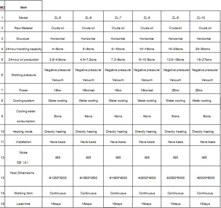
3. Models of waste lube oil distillation plant
4. Installation: We will be in charge of arranging our engineer to go to your place to guide the installation and train your workers how to operate the waste lube oil distillation plant ,and buyer will be in charge of the food, accommodation and round air tickets.
5. Waste Lube Oil Distillation Plant Exporting Experience:
|
America: |
Brazil, Canada, Colombia, USA, |
|
Middle East: |
Dubai, Iran, Jordan, Saudi Arabia, Turkey |
|
Europe: |
Albania , Bosnia and Herzegovina |
|
Asia: |
Afghanistan, India, Malaysia, Pakistan, Philippines, South Korea, Vietnam, Myanmar |
|
Africa: |
Ghana, Mozambique, Zambia |
Waste Lube Oil Distillation Plant
Waste Lube Oil Distillation Plant,Continuous Lube Oil Distillation Plant,Lube Oil Recycling Plant,Essential Oil Refinery Plant
Shangqiu Sihai Energy Technology Co., Ltd , https://www.sihaienergy.com