ã€Abstract】 This paper mainly introduces the application of HARSVERT series high-voltage frequency converters produced by Beijing Leader Huafu Electrical Technology Co., Ltd. on circulating fluidized bed boiler fans. It is applied to the Heshuyuan Power Plant of Meizhou Baolihua Group, mainly involving the transformation of Fans include: induced draft fans, primary fans, secondary fans, and vulcanized fans. Through the actual application of the field, the use of variable frequency speed control technology to control the air volume and air pressure of the fan system not only can play a role in energy conservation, but also can improve its control accuracy and shorten the response time, so that the fan system operation is more reasonable and reliable.
[Keywords]: high-voltage inverter, circulating fluidized bed boiler, induced draft fan, primary and secondary fans, fluidized fans.
The three forms of combustion of the boiler are: layer combustion (fire bed combustion), chamber combustion (suspended combustion), and boiling combustion (between the first two). Circulating fluidized bed is a boiling combustion method, so-called semi-levitation combustion method, suitable for burning granular solid fuels.
In circulating fluidized bed boilers, there is a large amount of bed material, artificially adding bed material when it is first started. The bed material is mainly composed of coal ash, unreacted limestone, and limestone desulfurization reaction products during the operation of the boiler. The bed material is in a fluidized state under the action of the primary air sent under the air distribution plate. The coal particles, bed material and limestone are carried upward in the furnace by the flue gas. At the different heights of the hearth, large particles will follow the furnace hearth. The wall falls, forming the internal circulation of the material; the smaller solid particles are entrained by the flue gas into the separator to separate, most of the particles are separated, some of the particles are directly returned to the furnace through the return valve, and the other part passes through the external heat exchanger. The furnace is returned to form the outer circulation of the material; the fly ash enters the tail flue with the flue gas. Through the internal circulation of the furnace and the external circulation outside the furnace, the continuous reciprocating cycle combustion of the fuel is realized.
2.1 advantages and disadvantages of circulating fluidized bed boiler technology:
Advantages: Good fuel compatibility, high combustion efficiency, low emission of gas pollutants, large load adjustment range, comprehensive utilization of fly ash and slag, etc.; circulating fluidized bed technology is the most mature and commercially available clean coal combustion Technology has been widely used in commercial applications for the use of inferior fuels and pollution control.
Disadvantages: Because of the unique air distribution device and the fly ash recirculation combustion system of the fluidized bed, the air pressure of the air supply system generally runs above 10 KPA. Due to the increase of wind pressure, the wear degree of the boiler heating surface, fire-resistant wear-resistant lining materials, and wind cap systems is higher than normal, the slag drop of the slag cooler is blocked, the coal particle size is too large, and the carbon content of the ash residue is too large. High temperature and steam temperature are difficult to guarantee. Due to the increase of wind pressure, the fans of the circulating fluidized bed boiler also have large power consumption and high resistance of the smoke duct. In general, the ratio of electricity for circulating fluidized bed boilers is at least 4%-5% higher than that for pulverized coal furnaces.
Wind smoke system of circulating fluidized bed boiler:
The schematic diagram of circulating fluidized bed boiler is as follows: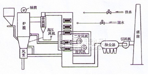
2.2 CFB fan system control difficulties:
Due to the unique combustion characteristics of the circulating fluidized bed boiler, the requirements for the control of air volume and air pressure are higher:
A. The normal fluidization of the material in the furnace is ensured by the primary air pressure and the air volume, and the air volume and the fuel volume must be matched to ensure the economy of combustion.
B. The amount of induced draft must be matched with the amount of air supply to maintain the furnace pressure within the normal range (usually a small negative pressure) to ensure the safety of the boiler. In order to ensure the fluidization of the material, the air pressure of the primary fan configured for the circulating fluidized bed boiler is relatively high.
Circulating Fluidized Bed Boiler Combustion Requirements The air volume of each fan above needs to be adjusted at any time to ensure normal and efficient combustion of the boiler. However, for the conventional design of the fan, the opening of the inlet deflector (ie, baffle or damper) is generally used to adjust the wind pressure and air volume. Due to the general design of air flow and air pressure, there is more margin than the rated operating conditions according to the demand. Therefore, the general selection of the air blower and the selection of the electric motor are too large. In operation, due to the change of the load, adjustment may be frequently required. The actual air damper opens. The degree is adjusted between 30% and 90%, and the linearity of the air volume adjusted by the damper is not good. When the damper opening degree adjustment is performed, an abnormal change in the air volume often occurs, and the response speed of the adjustment cannot keep up, increasing the difficulty of adjustment. . In addition, adjusting the air volume through the damper makes the fan often work in an inefficient area and wastes a lot of energy.
Third, the frequency conversion of circulating fluidized bed fan system for large-capacity circulating fluidized bed boiler, using a double fan system, the reliability requirements and common pulverized coal boiler, when a fan (frequency converter) failure, It will not cause the boiler to extinguish the fire, but it will cause relatively large disturbances and will take off part of the load. In order to reduce the disturbance to the minimum, the “one-on-one†automatic bypass control system is adopted for the frequency conversion of the primary and secondary blowers and induced draft fans of the large-capacity circulating fluidized bed blower, and for the dual-use and standby fluidization Fans, taking into account the economy, the use of "one-on-one" manual bypass control system, the following article briefly introduces the HARVEST series of inverter and two control systems in the circulating fluid bed fan applications.
3.1 Introduction of HARVEST series high voltage frequency converters: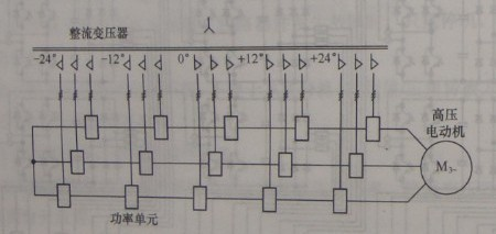
B. The power unit is the basic unit for the inverter to realize the variable-voltage and variable-frequency output. Each power unit is equivalent to an AC-DC-AC voltage single-phase output bottom-pressure frequency converter and outputs PWM waveforms with equal amplitude. However, each power unit has a definite phase shift between each other. After being superposed in series, a sinusoidal staircase PWM wave is obtained at the output side of the inverter.
C. The control of the frequency converter adopts DCS remote control. Through one-way 4-20MA analog, the output speed of the inverter is directly controlled to achieve the purpose of controlling the wind pressure and air volume of the fan. On the DCS side, automatic adjustment control is performed based on data such as load and furnace pressure through an automatic control program.
D. Inverter control power adopts two-way AC 220V power supply. The two power supplies are used for mutual backup. After one of the two power supplies loses power, undisturbed switching can be performed, and the alarm signal is sent to DCS to facilitate maintenance personnel troubleshooting.
E. Inverter cooling adopts air-cooled cooling and air-conditioning auxiliary cooling. Inverter heats hot air and exchanges heat through water cooler. It returns to the interior and continues to circulate. It is cooled by air-cooling method. There is no air exchange between the inverter room and the outside world. , To improve the environment of the frequency converter room. At the same time, in the later period of maintenance, the air-water cooling is correspondingly smaller than other heat-dissipating methods, such as the air-conditioning cycle and maintenance. In the inverter room, air conditioners are also installed. In the case where the air-cooled equipment is put into use normally, the air conditioner is only used as a backup.
3.2 "One-for-one" Manual Bypass Frequency Conversion Modification Introduction, the main application load is fluidized fan: As shown in the figure, the “one-for-one†manual bypass inverter consists of three manual tool gates. The inverter inputs the switch QS1, the inverter outputs the switch QS2, and the power bypass switch QS3. And there is a complete interlocking function between the three switchgears: the drive interlocks the mechanical interlocking of the gate QS2 and the power frequency bypass switch QS3. After one switch is closed, the other switch cannot be closed, mainly to prevent the two. When the two switches are closed at the same time, the reverse power transmission of the inverter causes the inverter power unit to be damaged.
The fluidized bed boiler of the circulating fluidized bed boiler is usually three to five, mainly depends on the structure of the furnace and the windy smoke pipe and the supporting fan power, the Polaroid Power Plant fluidized blower is three, in the normal operating conditions, it is dual-purpose and prepared. Among them, the standby fluidized blower inverter is in hot standby state, that is, the input switch QS1 and the output switch gate QS2 of the inverter are in the closing state, and the high-voltage switch QF is in the closing state, and the inverter is in the high-voltage live standby state, in other If there is a fault between the two fans or the inverter, the standby fan can be started at any time and put into use immediately. Then the faulty fan is taken out of service and overhauled, and then put in standby after the inspection is complete.
Since the fluidizing fan is a dual-purpose device, the standby fan can be turned on immediately after the failure of the fluidization fan, leaving plenty of time for maintenance. Therefore, taking into account the economic status, the “one-on-one†manual bypass system can be used to satisfy continuous production. Claim.
3.3 "One-for-one" Automatic Bypass Frequency Conversion Transformation Introduction, the main application load is induced draft fan, primary and secondary fan: As shown in the figure, the "one-on-one" automatic bypass inverter consists of two manual switchgears and three vacuum contactors. The inverter inputs the switch QS1, the input contactor KM1, and the inverter output switch QS2. Output contactor KM2, power frequency bypass contactor KM3. To repair the inverter, you can disconnect the manual switch QS41 and QS42 to form an obvious break point to ensure safety. During the inverter operation, close the KM41 and KM42. When the inverter fails, the system will automatically disconnect the KM41 and KM42, and close the KM43 by time. The motor runs in the power frequency state.
Although for a double fan circulating fluidized bed boiler system, in which one fan has a fault, the boiler will not turn off, and only the load reduction operation is required. In order to ensure the continuous operation of the system, the induced draft fan and the first and second fans adopt the “one to one†automatic bypass system. When the inverter fails, the inverter will automatically open the KM41 and KM42 and issue a “heavy fault†status. Signal to DCS, DCS receives the inverter "heavy fault" status signal, began to issue a shutoff command, when the throttle is closed to a certain degree of opening, the inverter automatically close KM43, this time the fan running at the power frequency state.
After a number of tests at the site, when the inverter fails, the throttle opening is preferably closed to about 30% of the best value. At this time, the fan is run at the power frequency state again, and the entire boiler system is The least impact. After many tests of the damper switching speed, the inverter's time for switching power frequency is determined. That is, when the inverter fails, it starts timing immediately and opens the KM41 and KM42, and sends a “heavy fault†signal to the DCS. The DCS starts. After executing the shut-off door logic, after 29 seconds, the damper is closed to approximately 30% opening. At this time, the inverter automatically closes the KM43 and the fan resumes the power frequency operation.
Therefore, for the induced draft fan, primary and secondary fan systems, when the inverter has a fault, there is only about 30 seconds of load pressure fluctuation time, which can be restored to the dual fan operation state. This will ensure continuous operation of the system.
There may be different operating conditions for different sites, and the mechanical action time of the possible dampers may not be the same. The HARSVERT series inverter can freely set the time for switching the power frequency from the interface to meet the operating conditions of different sites. Claim.
IV. Conclusion:
For the reformation of the inverter of the Baoshuhua Group Heshuyuan Power Plant, the frequency conversion of the circulating fluidized bed boiler fan system has achieved very good results, which facilitates the adjustment of the operating personnel. The operating conditions of the entire boiler are relative to the power frequency status. It is much more stable. Moreover, through frequency conversion, it also reduces the plant electricity ratio, and it has a very good energy-saving effect.
References:
[1] Yi Peng editor, high-voltage high-power inverter technology and application principles, People's Posts and Telecommunications Press, 2008.2 first edition.
[2] Edited by China Power Engineering Society, Technical Manual of Thermal Power Equipment, Beijing: Mechanical Industry Press, 1999.
[Keywords]: high-voltage inverter, circulating fluidized bed boiler, induced draft fan, primary and secondary fans, fluidized fans.
The three forms of combustion of the boiler are: layer combustion (fire bed combustion), chamber combustion (suspended combustion), and boiling combustion (between the first two). Circulating fluidized bed is a boiling combustion method, so-called semi-levitation combustion method, suitable for burning granular solid fuels.
In circulating fluidized bed boilers, there is a large amount of bed material, artificially adding bed material when it is first started. The bed material is mainly composed of coal ash, unreacted limestone, and limestone desulfurization reaction products during the operation of the boiler. The bed material is in a fluidized state under the action of the primary air sent under the air distribution plate. The coal particles, bed material and limestone are carried upward in the furnace by the flue gas. At the different heights of the hearth, large particles will follow the furnace hearth. The wall falls, forming the internal circulation of the material; the smaller solid particles are entrained by the flue gas into the separator to separate, most of the particles are separated, some of the particles are directly returned to the furnace through the return valve, and the other part passes through the external heat exchanger. The furnace is returned to form the outer circulation of the material; the fly ash enters the tail flue with the flue gas. Through the internal circulation of the furnace and the external circulation outside the furnace, the continuous reciprocating cycle combustion of the fuel is realized.
2.1 advantages and disadvantages of circulating fluidized bed boiler technology:
Advantages: Good fuel compatibility, high combustion efficiency, low emission of gas pollutants, large load adjustment range, comprehensive utilization of fly ash and slag, etc.; circulating fluidized bed technology is the most mature and commercially available clean coal combustion Technology has been widely used in commercial applications for the use of inferior fuels and pollution control.
Disadvantages: Because of the unique air distribution device and the fly ash recirculation combustion system of the fluidized bed, the air pressure of the air supply system generally runs above 10 KPA. Due to the increase of wind pressure, the wear degree of the boiler heating surface, fire-resistant wear-resistant lining materials, and wind cap systems is higher than normal, the slag drop of the slag cooler is blocked, the coal particle size is too large, and the carbon content of the ash residue is too large. High temperature and steam temperature are difficult to guarantee. Due to the increase of wind pressure, the fans of the circulating fluidized bed boiler also have large power consumption and high resistance of the smoke duct. In general, the ratio of electricity for circulating fluidized bed boilers is at least 4%-5% higher than that for pulverized coal furnaces.
Wind smoke system of circulating fluidized bed boiler:
The schematic diagram of circulating fluidized bed boiler is as follows:
Circulating fluidized bed boiler schematic
Circulating fluidized bed boilers are fed through a primary air blower (shared by one or two boilers, referred to as a blower or a blower), and the hot air heated by the air preheater is sent to the hearth, mainly in the fluidized furnace. At the same time, it provides the oxygen needed for fuel combustion in the dense phase zone of the lower furnace. For fluidized bed boilers with larger capacity, multiple fluidized fans are also specifically designed to act as materials in the fluidized furnace. At the same time, through the secondary fan, it provides the oxygen needed to make up the fuel in the furnace and enhances the mixing of the materials, and also the distribution of the temperature inside the furnace. The flue gas after burning in the hearth passes through the circulating ash separator and the fly ash returning device to circulate and burn the uncompleted flue gas. The exhaust gas finally passes through the dust collector and is discharged into the atmosphere through the induced draft fan. 2.2 CFB fan system control difficulties:
Due to the unique combustion characteristics of the circulating fluidized bed boiler, the requirements for the control of air volume and air pressure are higher:
A. The normal fluidization of the material in the furnace is ensured by the primary air pressure and the air volume, and the air volume and the fuel volume must be matched to ensure the economy of combustion.
B. The amount of induced draft must be matched with the amount of air supply to maintain the furnace pressure within the normal range (usually a small negative pressure) to ensure the safety of the boiler. In order to ensure the fluidization of the material, the air pressure of the primary fan configured for the circulating fluidized bed boiler is relatively high.
Circulating Fluidized Bed Boiler Combustion Requirements The air volume of each fan above needs to be adjusted at any time to ensure normal and efficient combustion of the boiler. However, for the conventional design of the fan, the opening of the inlet deflector (ie, baffle or damper) is generally used to adjust the wind pressure and air volume. Due to the general design of air flow and air pressure, there is more margin than the rated operating conditions according to the demand. Therefore, the general selection of the air blower and the selection of the electric motor are too large. In operation, due to the change of the load, adjustment may be frequently required. The actual air damper opens. The degree is adjusted between 30% and 90%, and the linearity of the air volume adjusted by the damper is not good. When the damper opening degree adjustment is performed, an abnormal change in the air volume often occurs, and the response speed of the adjustment cannot keep up, increasing the difficulty of adjustment. . In addition, adjusting the air volume through the damper makes the fan often work in an inefficient area and wastes a lot of energy.
Third, the frequency conversion of circulating fluidized bed fan system for large-capacity circulating fluidized bed boiler, using a double fan system, the reliability requirements and common pulverized coal boiler, when a fan (frequency converter) failure, It will not cause the boiler to extinguish the fire, but it will cause relatively large disturbances and will take off part of the load. In order to reduce the disturbance to the minimum, the “one-on-one†automatic bypass control system is adopted for the frequency conversion of the primary and secondary blowers and induced draft fans of the large-capacity circulating fluidized bed blower, and for the dual-use and standby fluidization Fans, taking into account the economy, the use of "one-on-one" manual bypass control system, the following article briefly introduces the HARVEST series of inverter and two control systems in the circulating fluid bed fan applications.
3.1 Introduction of HARVEST series high voltage frequency converters:
HARVEST series high voltage inverter typical structure
The HARVEST series of Beijing Leader Huafu Electric Technology Co., Ltd. is a series-connected multi-level high-voltage frequency converter, and uses multiple independent low-voltage power units in series to achieve high-voltage output, which mainly includes two parts: a phase-shifting transformer and a power unit. And supplemented by other control systems, such as the main control box, PLC, etc., so that the inverter's operating status can be recorded in real time, and there is a complete protection function A, phase-shifting transformer, the main function is to drop the input voltage to about 700V voltage, The power module is supplied, and through multiple designs, the harmonic currents of the windings on the secondary side of the transformer cancel each other, basically eliminating the harmonic pollution of the frequency converter to the power grid. B. The power unit is the basic unit for the inverter to realize the variable-voltage and variable-frequency output. Each power unit is equivalent to an AC-DC-AC voltage single-phase output bottom-pressure frequency converter and outputs PWM waveforms with equal amplitude. However, each power unit has a definite phase shift between each other. After being superposed in series, a sinusoidal staircase PWM wave is obtained at the output side of the inverter.
C. The control of the frequency converter adopts DCS remote control. Through one-way 4-20MA analog, the output speed of the inverter is directly controlled to achieve the purpose of controlling the wind pressure and air volume of the fan. On the DCS side, automatic adjustment control is performed based on data such as load and furnace pressure through an automatic control program.
D. Inverter control power adopts two-way AC 220V power supply. The two power supplies are used for mutual backup. After one of the two power supplies loses power, undisturbed switching can be performed, and the alarm signal is sent to DCS to facilitate maintenance personnel troubleshooting.
E. Inverter cooling adopts air-cooled cooling and air-conditioning auxiliary cooling. Inverter heats hot air and exchanges heat through water cooler. It returns to the interior and continues to circulate. It is cooled by air-cooling method. There is no air exchange between the inverter room and the outside world. , To improve the environment of the frequency converter room. At the same time, in the later period of maintenance, the air-water cooling is correspondingly smaller than other heat-dissipating methods, such as the air-conditioning cycle and maintenance. In the inverter room, air conditioners are also installed. In the case where the air-cooled equipment is put into use normally, the air conditioner is only used as a backup.
3.2 "One-for-one" Manual Bypass Frequency Conversion Modification Introduction, the main application load is fluidized fan:
The fluidized bed boiler of the circulating fluidized bed boiler is usually three to five, mainly depends on the structure of the furnace and the windy smoke pipe and the supporting fan power, the Polaroid Power Plant fluidized blower is three, in the normal operating conditions, it is dual-purpose and prepared. Among them, the standby fluidized blower inverter is in hot standby state, that is, the input switch QS1 and the output switch gate QS2 of the inverter are in the closing state, and the high-voltage switch QF is in the closing state, and the inverter is in the high-voltage live standby state, in other If there is a fault between the two fans or the inverter, the standby fan can be started at any time and put into use immediately. Then the faulty fan is taken out of service and overhauled, and then put in standby after the inspection is complete.
Since the fluidizing fan is a dual-purpose device, the standby fan can be turned on immediately after the failure of the fluidization fan, leaving plenty of time for maintenance. Therefore, taking into account the economic status, the “one-on-one†manual bypass system can be used to satisfy continuous production. Claim.
3.3 "One-for-one" Automatic Bypass Frequency Conversion Transformation Introduction, the main application load is induced draft fan, primary and secondary fan:
Although for a double fan circulating fluidized bed boiler system, in which one fan has a fault, the boiler will not turn off, and only the load reduction operation is required. In order to ensure the continuous operation of the system, the induced draft fan and the first and second fans adopt the “one to one†automatic bypass system. When the inverter fails, the inverter will automatically open the KM41 and KM42 and issue a “heavy fault†status. Signal to DCS, DCS receives the inverter "heavy fault" status signal, began to issue a shutoff command, when the throttle is closed to a certain degree of opening, the inverter automatically close KM43, this time the fan running at the power frequency state.
After a number of tests at the site, when the inverter fails, the throttle opening is preferably closed to about 30% of the best value. At this time, the fan is run at the power frequency state again, and the entire boiler system is The least impact. After many tests of the damper switching speed, the inverter's time for switching power frequency is determined. That is, when the inverter fails, it starts timing immediately and opens the KM41 and KM42, and sends a “heavy fault†signal to the DCS. The DCS starts. After executing the shut-off door logic, after 29 seconds, the damper is closed to approximately 30% opening. At this time, the inverter automatically closes the KM43 and the fan resumes the power frequency operation.
Therefore, for the induced draft fan, primary and secondary fan systems, when the inverter has a fault, there is only about 30 seconds of load pressure fluctuation time, which can be restored to the dual fan operation state. This will ensure continuous operation of the system.
There may be different operating conditions for different sites, and the mechanical action time of the possible dampers may not be the same. The HARSVERT series inverter can freely set the time for switching the power frequency from the interface to meet the operating conditions of different sites. Claim.
IV. Conclusion:
For the reformation of the inverter of the Baoshuhua Group Heshuyuan Power Plant, the frequency conversion of the circulating fluidized bed boiler fan system has achieved very good results, which facilitates the adjustment of the operating personnel. The operating conditions of the entire boiler are relative to the power frequency status. It is much more stable. Moreover, through frequency conversion, it also reduces the plant electricity ratio, and it has a very good energy-saving effect.
References:
[1] Yi Peng editor, high-voltage high-power inverter technology and application principles, People's Posts and Telecommunications Press, 2008.2 first edition.
[2] Edited by China Power Engineering Society, Technical Manual of Thermal Power Equipment, Beijing: Mechanical Industry Press, 1999.
Laundry Cart ,Shopping Basket & Cart,Hospital Cart ,Luggage Cart
Furnace And Feeder,Granulator And Coater Co., Ltd. , http://www.nbfeeder.com