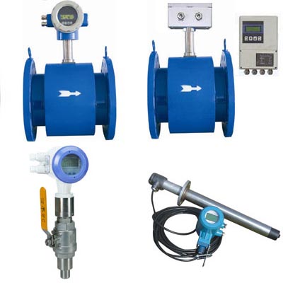
Electromagnetic flowmeter (Eletromagnetic Flowmeters, referred EMF) is the 1950s and 1960s with the development of electronic technology and the rapid development of new flow measurement instruments. The electromagnetic flowmeter is made according to Faraday's law of electromagnetic induction, which is used to measure the volumetric flow of conductive liquid. Due to its unique advantages, electromagnetic flowmeters have been widely used in the flow measurement of various conductive liquids in industrial processes, such as various acidic, alkali, salt and other corrosive media; electromagnetic flowmeters for various slurry flow measurement, Formed a unique application area. Structurally, the electromagnetic flowmeter consists of an electromagnetic flow sensor and a converter. The sensor is mounted on an industrial process pipe. Its function is to linearly convert the liquid volume flow value flowing into the pipe into an induced potential signal and send this signal to the converter through the transmission line. The converter is mounted not far from the sensor, it amplifies the flow signal sent by the sensor and converts it into a standard electrical signal output proportional to the flow signal for display, accumulation and regulation control.
  Electromagnetic flowmeter working principle
According to Faraday's law of electromagnetic induction, when a conductor moves in a magnetic field to cut a magnetic field line, an induced potential e is generated at both ends of the conductor, and its direction is determined by the right-hand rule. The magnitude and magnetic induction of the magnetic field B, the conductor is The length L in the magnetic field is proportional to the velocity u of the conductor. If B, L, and u are perpendicular to each other, then e=Blu(3-35) is similar. In a uniform magnetic field with magnetic induction B, a non-magnetic tube with an inner diameter D is placed perpendicular to the direction of the magnetic field. When the conductive liquid flows at the flow velocity u in the tube, the conductive fluid cuts the magnetic field lines. If a pair of electrodes (Fig. 3-17) are installed perpendicular to the diameter of the magnetic field on the cross section of the pipe, it can be proved that as long as the flow velocity distribution in the pipe is axisymmetric, an induced electromotive force is also generated between the two electrodes: e=BD (3-36) where is the average flow rate on the pipe section. The volumetric flow rate of the pipe can be obtained as follows: qv=Ï€DU= (3-37) As can be seen from the above formula, the volume flow rate qv is linear with the induced electromotive force e and the inner diameter D of the measuring tube, and inversely proportional to the magnetic induction intensity B of the magnetic field. Other physical parameters are irrelevant. This is the measurement principle of electromagnetic flowmeter. It should be noted that in order to make the formula (3-37) strictly established, the measurement conditions must satisfy the following assumptions: 1 the magnetic field is a uniformly distributed constant magnetic field; 2 the flow velocity of the measured fluid is axisymmetric; 3 the measured liquid is non-magnetic 4 The conductivity of the liquid to be tested is uniform and isotropic.
The installation diagram of the electromagnetic flowmeter should be installed at the lower part of the horizontal pipe and vertically upwards to avoid installation at the ZUI high point and vertical downward of the pipe; 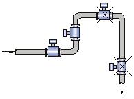
Should be installed on the rise of the pipe; 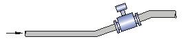
Installed in an open discharge pipe, which should be installed at the lower part of the pipe; 
If the pipe drop exceeds 5m, install an exhaust valve downstream of the sensor; 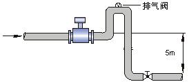
Control valves and shut-off valves should be installed downstream of the sensor and should not be installed upstream of the sensor; 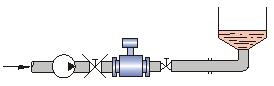
The sensor should not be installed at the inlet and outlet of the pump and should be installed at the outlet of the pump; 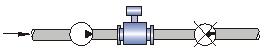
How to install a flow meter in a measuring well 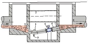
1. Inlet 2, overflow pipe 3, inlet grille 4, cleaning hole 5, flow meter 6, short pipe 7, outlet 8, and discharge valve. How to correctly select the installation node: Correct selection of the installation point and proper installation of the flowmeter are very The important link, if the mistakes in the installation process, the lighter affects the measurement accuracy, the heavy one will affect the service life of the flowmeter, and even damage the flowmeter.
Special attention must be paid when choosing an installation location:
The axis of the non-measuring electrode must be approximately horizontal; 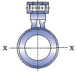
The measuring pipe must be completely filled with liquid; 
In front of the flowmeter, there must be a straight pipe section with a length of 5* D (D is the inner diameter of the flowmeter), and a small straight section of 3*D (D is the inner diameter of the flowmeter) in the rear;
The flow direction of the fluid is consistent with the direction of the arrow of the flowmeter; the vacuum inside the pipe will damage the inner lining of the flowmeter, and special attention should be paid; there should be no strong electromagnetic field near the flowmeter; there should be sufficient space near the flowmeter for installation. And maintenance; If the measuring pipe has vibration, there should be a fixed bearing on both sides of the flowmeter to measure the mixed liquid of different media. The distance between the mixing point and the flowmeter is less than 30×D (D is the inner diameter of the flowmeter) The length is to facilitate the cleaning and maintenance of the flowmeter in the future, and the bypass pipe should be installed; 
When installing the PTFE-lined flowmeter, the bolts connecting the two flanges should be evenly tightened, otherwise the PTFE lining may be easily crushed, and the ZUI uses a torque wrench.
PET Preform Mold,PET Preform Injection Mold,PET Preform Mould,PET Preform Injection Mould
Demark(changxing)injection system CO. LTD , https://www.petplas.com